One of the things that I feel will be consistently true throughout my life is that there are more things that I'd like to do than I will have time for. Across my personal and professional life, many of these look a lot like large projects. Whether I'm working on the next major software project for work, a website or mobile app I'm building for fun or profit, a ridiculous art project for BurningMan, some kind of home improvement activity or any thing else, the reality of limited resources (particularly my own time and the time of my collaborators) will be one of the greatest limiting factors.
I've found that in order to be effective and to actually finish projects (and finish them in a meaningful way) there are two things that I need to do:
1) Set a deadline
2) Define exactly what will get done.
Most projects have some kind of deadline built in. For a moment, let's assume that you have a deadline intrinsic in the project, and for simplicity's sake, let's assume that there's only one (the "all-up done" deadline. (Though we all know that for complex projects that's a vast simplification)
This still leaves the question of how we define what will get done. I recently learned a framework for thinking about this problem which I have found to be incredibly clear and useful. Since learning it, I've explained it to folks on each project that I've worked on, and I've found that it has taken root, and been incredibly effective at driving clear, meaningful conversations in areas which were previously dangerously ambiguous.
This taxonomy is as follows:
P0 – These are items we will NOT ship the product without. If it comes to a decision between a P0 item and our date, our date moves. That’s the definition and bar for what a P0 item is. Clearly we cannot have more P0 cost than we have time in our schedule (simple physics). Likewise, it would be somewhat irresponsible to have the P0 cost be very close to our total time… We should have some buffer there, or we can expect our ship date to move (also physics). Ordering our P0’s relative to each other is not a super useful exercise, because we’ve already stated they’re non-negotiable. We still need to work through dependencies, and determine when things need to go in, but we’re not in the business of trading off P0’s against each other.
P1 – These are items that we would LIKE to ship with, and that we PLAN to ship, but if it comes to a decision between a P1 item and our date, the item will slip to the next release, and we will not move our date. Which items we do in this bucket will likely be the most contentious question. After pulling the P0 costing out of our schedule, there will be a relatively small block, and so there probably won’t be a lot of space in the P1 bucket. Ordering these is also important, because we will have to trade these off against each other throughout the project. As we recognize more complexity or cost in the items we’ve allocated to P0 that will naturally result in P1 items dropping off the list, and it’s important that those decisions be made in a consistent framework.
P2 – These are items that we will NOT ship this release with, but that we would LIKE to ship in the next release or two. These items should be considered from an architecture perspective during design that supports P0 and P1 items, to ensure we do not architect ourselves into a corner which makes it very HARD or EXPENSIVE to do these features later.
P3 – These are items which we do NOT plan to ship for the foreseeable future. They are captured for consistencies sake, and so that there is a clear list of non-goals. Any time one of these comes up, we can point people at the P3 item… Yup, we’ve thought about it, and we’re not doing it.
This taxonomy was proposed to me by Alex Frank, one of the architects in my group at work, and since adopting it, I've been pleasantly surprised by the amount of use I've gotten out of it. I've explained it to many people, and it's been common for them to follow up asking for the written description, and then to have them adopt it for their own projects. Given all that, it seems like a powerful set of ideas, and I figured I'd drop it here so that more folks could see it. :)
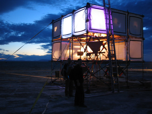
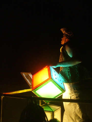
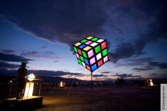
I was part of Camp Groovik, which brought a gigantic, illuminated, fully interactive Rubix cube to the Burning Man art festival. The project was named “Groovik’s Cube”. (Get it? J) I was the software lead, and architected and drove the development of the software stack which supported the device. I was fortunate enough to work with an incredibly talented group of people, both within my software team (consisting of 5 people), and across the entire project. First a picture… (from Gizmodo)
Some stats on the project:
The cube was 15’ by 15’, weighed over 4600 lbs, and was balanced on a 4 inch wide, 10 foot tall pole, and held stable by guy wires in 9 directions.
There were contributions from 70 people, totaling over 5000 man hours that went into the project before we left for the festival, a bit over 500 man hours of construction time once we were there, and another 500 or so hours manning, maintenance, and finally deconstruction. It was an $18,000 project, not counting people’s time.
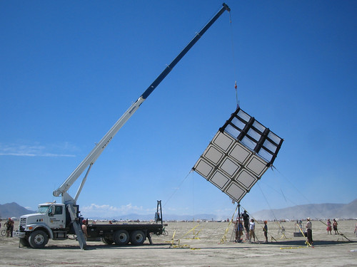
Here’re a couple of shots of construction, including the lifting…
The internal structure of the cube was made from system scaffolding, and a custom built mast that divided into 3 pieces and ran from the ground, all the way through the top point of the cube. The outer (visible) parts of the cube were made of two types of fabric. The black lines are formed from a black spandex material, and the facets are made from a rip-stop nylon. Each facet is individually attached to the scaffolding around it by 4 ropes wound through 9 grommets on each side of each facet, and the outer black strips are then held on by Velcro.
The major hardware components in the electronics stack were as follows:
2 RGB Ultrabrite LEDs per facet.
11 light boxes. Each light box drove 5 facets and contained:
A microcontroller (Arduino board) each of which drive the PWM signal creation for the 5 facets being driven by this lightboard
2 computer power supplies. (This is the part deemed most likely to fail given the conditions, so we built in redundancy)
A custom designed and manufactured board which manages drawing and unifying current from the two computer power supplies, and manages failover if one dies. This board also has output pins that tell us the current state of the two power supplies. These pins were wired across to the micro-controller, which in turn relayed the data back to the CPU so we could have remote telemetry. (More on this later)
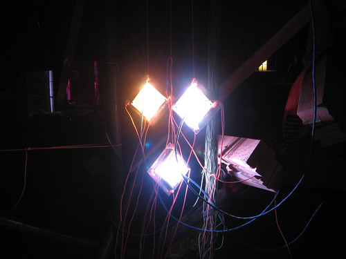
A custom designed and manufactured board (dubbed the “Lumier”) which managed combining the power from the power board, and the signal from the micro-controller to actually drive the 2 RGB leds as a single light unit. The lights pointed backwards into a mylar sheath, so all lighting was indirect, which gave us the Matte coloring we were looking for. Here’s a shot of the lights without the reflector
Each light box had all of the components mounted on a wood block, and then isolated in a tupperware container, with all wires coming out of the box through a tube to prevent dust from entering. You can see one of these units in the picture below. (You can also see the back of several reflectors):
2 Gumstix computers, one to act as the CPU/brain of the cube, and one to act as an audio server. (Each the size of a stick of gum… really!)
3 JBL Studio monitor speakers
1 Mixer
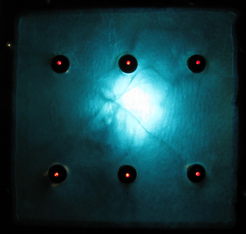
3 UI stations, each of which contained
6 Dustproof buttons (Amazing how hard these are to find) with a controllable LED on each button
A microcontroller (another Arduino board)
Some lights (not addressable)… These are just for illumination. J
Some custom wiring to connect the buttons to inputs on the microcontrollers
A custom designed and welded steel frame, which contained the lights, and had a cube oriented in the same way as the cube that was being controlled…
Sanded plexiglass to get the frosted cube look… (Gels on the back to give us color…)
2 Levels of USB hubs, (4 hubs total) to get us out from the CPU to all microcontrollers that drove facets
1 wireless Ethernet switch which allowed the CPU and sound server to talk, allowed the CPU and UI stations to talk, and allowed us to log in for remote control and telemetry.
Major software components that had to be written included:
A sound server which:
Runs on a separate Gumstix computer, connecting over Ethernet to the main computer
Manages sound mixing, streaming, and time stretching.
MicroController control code which runs on each UI station (the small stands around the cube), which:
Debounces the signals from the buttons
Manages acquiring and maintaining a connection over Ethernet to the CPU.
Sends button press info to the CPU,
Responds to commands from the CPU to turn the button LEDs on or off, depending on whether the cube was willing to accept input
Micro Controller code which Drives the facets
Creates the PWM signal on three output pins per LED
Gives us 24 bit addressable color space, mapped into exponential space so that a linear step command mapped to a linear perception step
Accepts commands over a custom protocol built on top of USB.
Commands look like: Send facetX to color (R,G,B) with a smooth linear interpolation over N milliseconds
Sends responses to the CPU which explained current state, as well as the power supply state
The cube simulation which:
Handles the internal cube state
Queues and executes rotations
Logs every move it ran through
Has additional “Special” animations which could be driven through for things like the reward sequence.
Recognizes states (like “one side solved” or “whole cube solved”) which tie back to reward sequences of some kind.
The display driver which:
Manages mapping from the 54 pixel representation, out to the commands sent to the microcontrollers
Handles the mapping to allow us to have an arbitrary relationship between pixel ID and lightbox controller that was driving it.
Handles connections out to the microcontrollers, including the ID process… Ask me about that if interested. J
The control driver which:
Manages inbound Ethernet connections from each UI station
Maps from button presses to “cube centric commands”
Handles Multi-press to allow for more complex command processing
Commands the button LEDs on and off to indicate the willingness of the model to accept input.
Telemetry, configuration, etc…
A series of text files that the program read and wrote which allowed us to parameterize it’s operation in various ways
Telemetry which told us the current state of the power supplies…
All programmed over SSH, over wireless… *(You could use an IPhone!)
The program scaffolding which brought everything together, and made it all run…
Finally, a couple of my favorite pictures:
The one unfortunate thing was that the sun is too bright to run this object during the day… But it was still quite striking. J
All code for the micro-controllers was written in C, and all other code was written in Python (which was a lot of fun, since I’d never written anything in Python before). For anyone who’s interested, code is all up on SourceForge, and released under an open source license.
We had solves every night, starting Tuesday.
I led a team that solved the cube on Thursday night.
Here's a video of the cube celebrating after it's been solved:
Alright, this is the obligatory "I'm starting a blog" post. This has been on my todo list for far too long, and over the years, I've noticed that I send more and more of the writeups that I do on various topics and projects to more and more people. The point-point communication model isn't really scaling for me, and so I'm switching to broadcast. :)
Topics: What I find interesting. In general, that means that I'm likely to blog about a strange combination of things like computer security, mobile application development, electronics hacking, interactive art projects, ultimate frisbee, electronic music, automated music analysis and generation, video games, weird science, nutrition science, education, healthcare, and probably some other (even more random topics).
Frequency: I guess we'll see. :) I've got interesting stories and projects in each of these areas, so I definitely have a backlog of posts to write. It'll be interesting to see which of them I bang out in what order. I'm looking forward to this, and to all those folks out in the ether... perhaps you'll find it interesting too.